Modifiers | 3D Modifiers
3D Modifiers
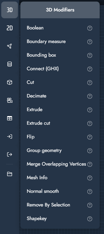
3D modifiers operate on three-dimensional geometry and are used to create, modify, optimize, or combine meshes. They include operations such as boolean logic, extrusion, decimation, smoothing, and mesh analysis.
These modifiers form the core of 3D geometry processing within TwikBot and are commonly used before visualization or export.
Modifier | Explanation | Input |
|---|---|---|
Boolean | The boolean modifier performs a boolean operation between two geometry objects. Depending on the selected mode, the result can represent the union, subtraction, or intersection of the two inputs. | 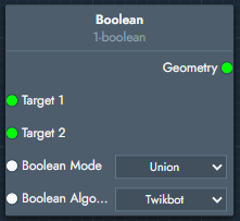 Inputs
Outputs
|
Boundary measure | The boundary measure modifier calculates the size of the object along the selected axis and outputs the bounding dimension values. | 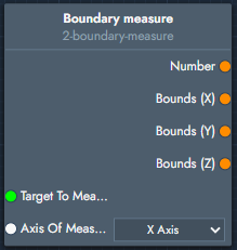 Inputs
Outputs
|
Bounding box | The bounding box modifier creates the bounding box of the target object. Optional offsets can expand or shrink the box along each axis. | 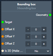 Inputs
Outputs
|
Connect (GHX) | The connect modifier links a GHX (Grasshopper) CAD source into the graph and retrieves geometry from it. More information on how to link GHX scripts can be found here: Graph Editor | Connect with Rhino Grasshopper | 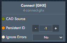 Inputs
Outputs
|
Cut | The cut modifier cuts geometry using another geometry object as the cutting tool. | 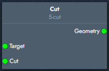 Inputs
Outputs
|
Decimate | The decimate modifier reduces the polygon count of the object while attempting to preserve its overall shape. | 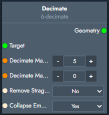 Inputs
Outputs
|
Extrude | The extrude modifier extrudes geometry along the vertical direction and optionally controls depth and segmentation. | 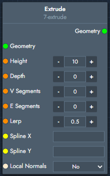 Inputs
Outputs
|
Extrude cut | Extrudes the faces produced by the cut modifier to create an emboss or deboss. | 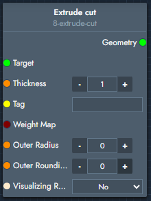 Inputs
Outputs
|
Flip | The flip modifier reverses the orientation of the geometry. | 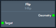 Inputs
Outputs
|
Group geometry | The group geometry modifier combines multiple geometry objects into a single geometry output. | 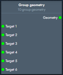 Inputs
Outputs
|
Merge Overlapping Vertices | The merge overlapping vertices modifier merges vertices that fall within the defined tolerance. | 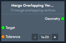 Inputs
Outputs
|
Mesh Info | The mesh info modifier outputs mesh statistics such as vertex count, edge count, and face count. | 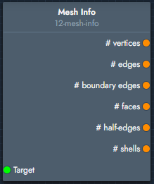 Inputs
Outputs
|
Normal smooth | The normal smooth modifier smooths geometry normals using the provided maximum angle threshold. | 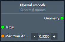 Inputs
Outputs
|
Remove By Selection | Remove all selected or unselected faces of a geometry. Commonly used in combination with the cut modifier to separate the resulting geometry. | 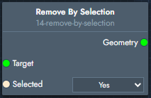 Inputs
Outputs
|
Shapekey | Creates a variable geometry using linear morphing, a technique where each point (vertex) in the geometry gradually translates from one location (defined by the first mesh) to another (defined by the second mesh). To make this work, the starting geometry and the final geometry must have the exact same number of vertices, and these vertices must appear in the same order in both meshes. The value entered in the interpolation field determines the factor by which each vertex is translated. | 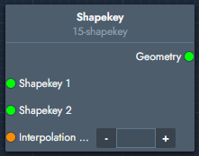 Inputs
Outputs
|